An introduction
This document is a revision to one created by DEWESoft USA in 2021. It takes that basic document which is related to a specific Negative Temperature Coefficient (NTC) thermistor and widens it scope with some details and information to allow any NTC thermistor sensor to be used.
As the name suggests, Thermistors are resistance-based devices used to measure temperature. They have some advantages over thermocouples and other resistive temperature devices (RTD) but have been less-frequently used in the past – probably due to wiring complexity and non-linear response. Unlike RTDs, which are made from pure metals, Thermistors are semi-conductor based.
This document presents two ways that NTCs can be incorporated into DEWESoft-based measurement systems.
Operating principles
An NTC thermistor is one where the resistance decreases with temperature, while a PTC one has an increasing resistance with temperature. These two responses allow thermistors to be used in differing applications: NTCs are used as temperature sensors or as inrush current limiters in series with another device; PTCs are often used to protect against overcurrent by connection in series with another device (as a “resettable fuse”).
An important feature of a thermistor is its base resistance at a “room” temperature of 25 °C. This value can be 2 kΩ, 10 kΩ, 100 kΩ or other value depending on the manufacturer. In addition, each thermistor will have a B value which describes the gradient of the resistive curve over a range between two temperature points. This can then be used to generate a table of temperatures and resistances using the exponential relationship between temperature and resistance.
As with strain gauges (where resistance changes related to material extension/compression are quite small), thermistors are placed in Wheatstone Bridge configurations in order to generate a voltage signal proportional to the change in resistance. In order to use a thermistor with DEWESoft hardware, it must be wired with a precision reference resistor of the same value as the base resistance (R25) of the sensor.
Obtaining temperature values
There are two ways of determining temperature from a thermistor: one is to create a sensor within the Analog Sensors database and make use of a table relating temperature and Wheatstone Bridge voltage signal; the other is to calculate the resistance and use the “Steinhart-Hart” equation for the sensor.
Analog Sensor Database (look-up table)
Each thermistor manufacturer will provide a relationship between resistance and temperature – possibly in the form of a datasheet with the sensor’s characteristics (“B” value) and leave it up to the end user to create a table of resistances and temperatures; possibly in the form of a table on the sensor’s datasheet or perhaps as a resource on the website. Whatever the source of the resistance/temperature table, a relationship between mV/V and temperature needs to be created for subsequent import into the Analog Sensor database.
Here is an extract of a TDK thermistor whose base resistance at 25 °C is 10 kΩ:
For the Analog Sensor database, we need to ensure that our “X” values (i.e. output in mV/V) is in ascending order and this is calculated from the standard relationship between resistance and voltage signal (in mV/V) for a Wheatstone Bridge:
1000×(Rt /(Rt + R25) -0.5)
Where: Rt is the resistance at the temperature of interest; and R25 is the base resistance (10 kΩ at 25 °C in this case). Note the inclusion of the 1000 factor to ensure our units are mV/V.
Using this equation and reordering so that our most negative voltage signal is first, we get the following relationship for the table above:
In order to import into the Analog Sensor database, it is important to include the “x” and “y” rows from the calculation table. It is beyond the scope of this document to go into every detail of the Analog Sensor Database, but here is the end result of incorporating the above table:

Steinhart-Hart Calculation Approach
The Steinhart-Hart approach requires three temperatures and their corresponding resistance values. These could, in principle, be measured values or taken from the sensor datasheet. Ideally, the three temperatures will correspond to the lowest of interest, the highest of interest and one somewhere in the middle. Three coefficients (A, B, C) are then calculated which are then used with the Rt value to allow a temperature to be derived.
As the relationship is exponential, the natural logarithm of the Rt value (calculated from the Bridge signal voltage) is needed. The value of Rt must always be greater than zero to ensure a valid calculation. Revision 1.0 of this document used a specific NTC thermistor and normalised the temperature-related resistance to the R25 value. In that specific case, the normalised value was always a positive number (resulting in a valid logarithm to be calculated). This version of the How To guide should, in principle, allow any thermistor to be used with DEWESoft hardware and software.
The Steinhart-Hart equation (in °C) is:
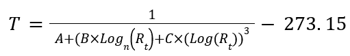
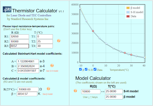
We can use an SRS Thermistor calculator to calculate these values.
Using a selection of resistances from the table above for the TDK sensor, we can obtain the following coefficients:
With a little extra effort, a second set of coefficients can be calculated, say, for the higher range of interest and a “condition” channel calculated – depending on the resistance value. The following paragraphs show all of the details.
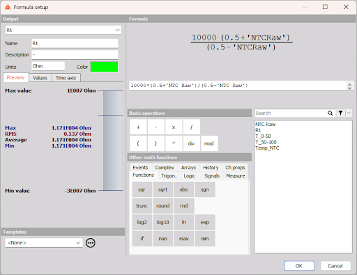
We need to revert to a V/V scaled value, so the Analog set up needs to be configured like this: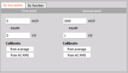
Using the standard Wheatstone Bridge equation, we can derive the value for Rt as:
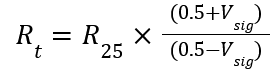
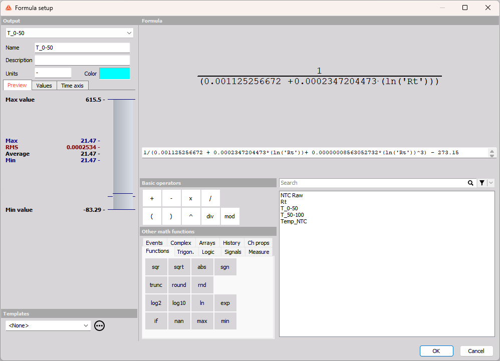
With Rt and the Steinhart-Hart coefficients, we can calculate the temperature for one or more ranges of interest. In the following example, the Bridge Signal Voltage is called “NTC raw”:
Steinhart-Hart coefficients were calculated using two sets of temperatures: 0/25/50 and 50/75/125 to generate the following temperature calculations:
- For lower temperatures:
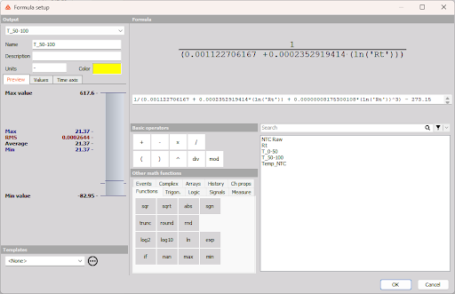
- For higher temperatures:
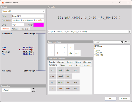
Finally, a resistance-based test to determine which version of temperature should be used:
DEWE-43A Wiring and Analog Input Settings
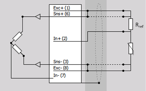
When using the DEWE-43A, a BRIDGE-QH-350-10V adapter can be used to provide the second half of the Wheatstone Bridge. When using an NTC, the sensor and reference resistor need to be wired as shown below:
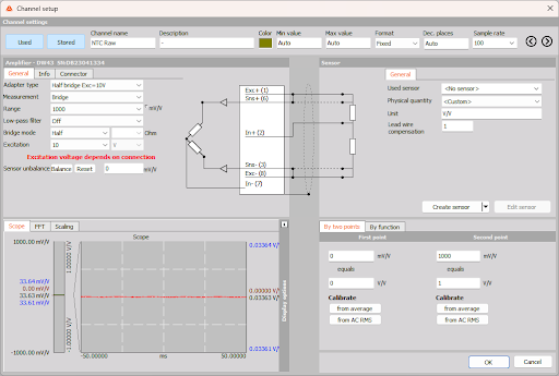
The rest of the Analog input settings look like this:
SIRIUS STG/STGS/STGM Wiring and Analog Input Settings
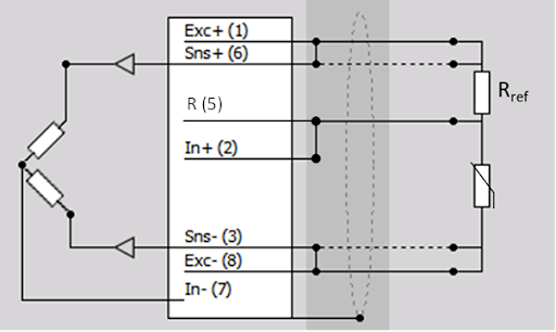
As the SIRIUS slices have built-in bridge completion resistors and different options for bridge supply voltages, the wiring is slightly different to the DEWE-43A and looks like this:
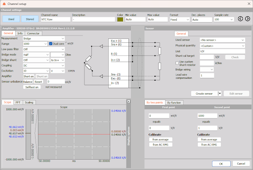
The rest of the Analog Input settings look like this:
John Huxtable, 15.9.2025